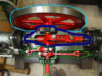
The wheel in light blue would be built by Kevin, the dark blue components in the centre and the exhaust/governor at either side would be built by Dan, and Teresa would build the components in green. My job would be to build the cradle the engine was placed in.
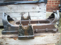
First, I required a reference plate image to work with. Luckily, Teresa had provided one as part of her additional research:

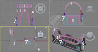
As can be seen, the chassis contains a lot of symmetry which made modelling easier. Below is my model in Max:

I will explain the model in sections:
1: "Loop at the top": The arch at the top of the model was a Torus which was converted into an Editable Poly. The bottom half was then removed and the remainder was scaled to fit.
2: "L shape section": This section was drawn using the Line tool and the main face was extruded to create a solid object. However, extruding the face led to a hole on one side of the model, so it was cloned and rotated to create a solid, filled L shape. This was then cloned 4 times around the model.
3: "Top section cover": This was created using the Line tool as well, and was extruded to give it depth so it extends to the bottom of the model. As can be seen, this was mirrored onto the other side of the chassis to create a bowl.
4: "Bowl": This Torus was added to the top of section 3 to smooth the edges out around the bowl.
5: "Back": This cube was added to the bowl section in the centre to provide a solid back and front section. As can be seen, it was cloned to opposite end of the model.
6: "Base": The base was a basic cube to provide a bottom to the model.
7: "Side supports": This section was mostly created using the Line tool and extruding faces to provide an approximation of the supports on the chassis seen in the photograph. Using the Line tool was a very complex way to do this and the sheer amount of cloning and rotating required told me I should have done this another way. The Torus in the centre is to smooth out the edge of the hole.
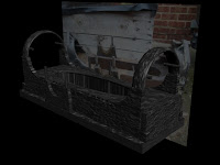
The screws around the model are cylinders placed in the correct position. The finished chassis with a very rough texture map looked like this:

The next job was to join everybody's sections together into a coherent model.
No comments:
Post a Comment