Tuesday, 24 November 2009

Group Work- Environment

With the model built; textured and animated, the next step was to place it in the environment.

The environment was based on the Bedwas Coal Works in Monmouthshire, where the machine was housed in an outdoor "brickhouse", connected to tar tanks so it could pump the tar up a delivery pipe and into a vehicle. The first stage of building the environment was to obtain some designs, which Teresa had obtained from a former member of staff at the coalworks:


I then began building the environment in 3DS Max, starting with the basic plane floor and cube walls, which I textured using the brick and stone textures and bump maps from my original "factory" environment. The textures had to be tiled differently for each object they were applied to due to the different aspect ratios of the surfaces.


Using cylinders, I could create the masses of pipework which run above the tanks, as well as the supports for the tanks. The tanks themselves are "oil tank" primitives contained within cubes to simulate the cages.

To create the mesh texture for the cages, I made a metal texture in Photoshop and an opacity and bump map to go with it:


The next step was to texture the tanks, add some more pipework and texture it:


I felt the tanks should have a toughened, steel look to them so I created the following texture and bump map:


This was created from the following photo I had taken:


The pipework uses the same texture which was used for the pipes on the model. With the brickhouse complete, I felt it needed some scenery so I created some hills:


The hills were created by creating a single plane then using soft selection to mould it into a hill shape:
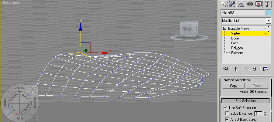


I then cloned this plane to surround the environment and created a flat plane below the stone area to act as ground:


To make the grass texture, I used another photo I had taken and also created a bump map:


With the main landscape complete, I added a sphere mapped with a double sided material to act as a skybox. The texture used for this was found on the internet:


Finally, I added some extra details such as a tunnel, rail track and a small house:


The tunnel is a cylinder which clips into the hillside. The texture and bump map applied to the cylinder is the same as that on the brick walls. In front of the cylinder is a plane with the following original texture and opacity map applied:


The building is a cube with a pyramid on top, to which I applied the UVW Unwrap modifier so that I could use a UVW Map template to ensure textures all sides of the building were upright:


Above is the roof texture. The roof texture and windows on the house were both adapted from this photo I took:


The rail track has the following texture and bump map I have created:
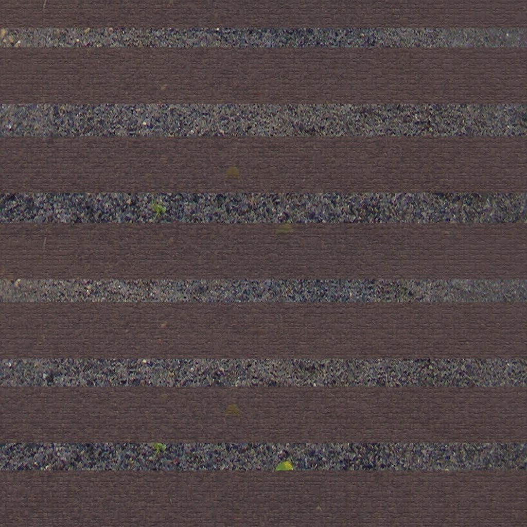


The underlying gravel texture:


Came from this photo I took:


The last stage of the environment was lighting. A single Omni light with ray traced shadows placed high above the scene sufficed. With the environment complete, the final 3D stages were putting the model in the environment and animating the camera movements.


The environment was exported as a 3DS file and imported into the steam engine's Max file to preserve the animation applied to the engine. Once placed in the Max file, the textures had to be reapplied to the environment and the environment itself was scaled to create a realistic image. The final scene was hugely demanding on computing power, with 100 frames taking 2 hours to render in Mental Ray and the final 40 second render took 13 hours.

Group Work- Model Textures

The next step of the animation was to apply textures to the model. I created the following in Photoshop and applied the bump map from the stone floor texture to some of them in order to give the images some "texture":


Above - The green texture for the governor housing.


Above - The exhaust housing texture.


Above- The chassis texture.


Above- The red wheel and component texture. There are two shades of this to differentiate between red components which sit next to each other.


Above- The texture used for pipework in both the model and the environment.


Above is the gauge image, taken from a photo I took at the museum next to its opacity map so the white edges are not visible on the model. It is not a very detailed or precise texture but it serves its purpose in the animation.

Below are images of the model with textures applied:


The next step was to place the model in the environment I had created. All aspects of creating the environment will be covered in the next section.

Group Work- Animation and More Alterations

Once Dan had completed the exhaust section, our model was complete. A further alteration to my chassis was made - the loop at the top was replaced by a new segment created by Dan as my loop did not fit the side sections exactly. Below is an image by Dan of the finished model showing everybody's contributions:


Upon receiving the first video of the animation loop from Kevin...


...It was good to see most of the animation in place. However, certain changes needed to made, which I did in class. The changes I made are:

- On the pump section in the centre, there are floating objects moving alongside Dan's main pump. These should be attached to the pole and not moving, so I removed the keyframed animation for these components.

- The block between Dan's animated object and Teresa's non moving section at the front should be moving. I animated this block and cloned it onto the other side of the central pump so both blocks moved the same way. Also, the blocks' rotation should reverse when they rotate by 90 degrees so I added this as well.

- Teresa's section at the front should be animated and both halves should move the same direction. I animated this front section.

Below is a video showing the completed animation loop. It contains the environment and textures, which will be discussed later:


As can be seen, there are no floating objects; the blocks rotate together and change direction once they have rotated 90 degrees; and Teresa's objects are animated.

Group Work- Combining and Alterations


Above are the first images of everybody's contributions to the model put together with the exception of the exhaust, which Dan had yet to make. Putting the model together was achieved as a group effort in class and involved a lot of scaling and moving of models to fit the sections together.

As far as alterations to my chassis were concerned, I removed the awkward-looking top of my side sections and replaced them with supports made by Teresa. Also, the bottom half of my side section was extruded further to provide a more accurate shape with more depth.

After this image was rendered, the next step was to include Dan's exhaust and email the finished model to Kevin for animation.

Group Work- Modelling the Engine

Since the last meeting, it had become apparent that Dan could not model the entire engine alone and Teresa did not feel comfortable building the governor, so we divided the engine up into parts to model:


The wheel in light blue would be built by Kevin, the dark blue components in the centre and the exhaust/governor at either side would be built by Dan, and Teresa would build the components in green. My job would be to build the cradle the engine was placed in.

First, I required a reference plate image to work with. Luckily, Teresa had provided one as part of her additional research:


As can be seen, the chassis contains a lot of symmetry which made modelling easier. Below is my model in Max:


I will explain the model in sections:

1: "Loop at the top": The arch at the top of the model was a Torus which was converted into an Editable Poly. The bottom half was then removed and the remainder was scaled to fit.

2: "L shape section": This section was drawn using the Line tool and the main face was extruded to create a solid object. However, extruding the face led to a hole on one side of the model, so it was cloned and rotated to create a solid, filled L shape. This was then cloned 4 times around the model.

3: "Top section cover": This was created using the Line tool as well, and was extruded to give it depth so it extends to the bottom of the model. As can be seen, this was mirrored onto the other side of the chassis to create a bowl.

4: "Bowl": This Torus was added to the top of section 3 to smooth the edges out around the bowl.

5: "Back": This cube was added to the bowl section in the centre to provide a solid back and front section. As can be seen, it was cloned to opposite end of the model.

6: "Base": The base was a basic cube to provide a bottom to the model.

7: "Side supports": This section was mostly created using the Line tool and extruding faces to provide an approximation of the supports on the chassis seen in the photograph. Using the Line tool was a very complex way to do this and the sheer amount of cloning and rotating required told me I should have done this another way. The Torus in the centre is to smooth out the edge of the hole.

The screws around the model are cylinders placed in the correct position. The finished chassis with a very rough texture map looked like this:


The next job was to join everybody's sections together into a coherent model.

Group Work- Dividing Work and Presenting

The next task was to divide the work up between the group. We decided this in our second group meeting (minutes by myself):

- We decided to model a Joseph Evans Reliable Steam Engine (pics and info can be found here http://www.steampumps.net/JosephEvansReliable.html).

- It was decided that we would each be responsible for a part of project but if any one of us struggles, we can share the workload.


- I will be designing, modelling and texturing the main environment the machine will be in- probably a factory of some sort similar to the museum.

- Teresa will be building the governor on the engine.


- Dan will be mainly building the mechanicals of the engine, however we will divide the model up and work on different parts each.


- Kevin will storyboard the animation, design and add lighting, and animate the scene.


- We also discussed the presentation on Friday. Although I will not be present for this due to prior arrangements, as a group we feel there is enough to talk about as we know what we are doing, who is doing it and how we will present the product. - Within the next week, we are all going to research the steam engine, prepare for the presentation, and I will begin designing the environment.

After this meeting, I began designing an environment - not knowing it had to be based on where the machine was actually used, not just a generic factory. Below is my initial design:


My first draft of the environment looked like this:


All the textures are original except the skybox. Below are the ones I created:


This brick texture was created from a photograph I took in Castle Coch in Wales:


The stonework texture below...


...Was adapted from this photograph I took in the same location:


I then created bump maps of these images in Photoshop by applying a plain grey image on a layer above the image, then applying a High Pass filter to the grey. The bump map for the stone texture was also used as the ceiling diffuse map and the stone floor was also used for the supports in the corners.

I was then informed the environment had to be representative of the environment the device was actually used in. Luckily, the textures could still be used for the new environment. First, however, there was the task of modelling the engine to deal with...

Virtual Environments Group Work- From the Start

For the group project, I was with Dan; Teresa and Kevin. The brief was to simulate in 3D an artifact from the Langdon Museum of Power to show where the machine would have been used and what it was for.

After a visit to the museum to take reference photos and videos of various machines to give us a basic idea of what they looked like and how they worked, we met as group to choose an engine. The minutes from the first group meeting, by Kevin, are below:

Minutes from meeting
- We arranged a group meeting for Monday October 5th at 10 AM
- All group members attended this meeting
- We discussed what we believe would be the best way to approach the task in hand
- We discussed what pictures we liked from the collection that we had taken
- We discussed what we could do for each picture that we liked and then narrowed it down working out whether it would be too much work, too little work, or just not within our knowledge of 3dsMax
- We also discussed how best to share work among each other, decision to use Dropbox was made
- Another visit to the museum was discussed, and the time allowing we will hopefully revisit
- The machine that we decided we would most likely be modelling is the "reliable steam engine"

To summarise, we chose the Joseph Evans Reliable Steam Pump, which was placed near collieries and was designed to pump tar from storage tanks to road or rail vehicles for transport.


Our initial visit to the museum had produced many helpful images and videos of the engine. However, Teresa's extra research such as revisiting the museum to obtain more detailed images; corresponding with people who worked with the machines and obtaining designs of the location the engine was used in was invaluable.